Aliantec
Industries Marine Renewables & H2 Aerospace & space Automotive & e-mobility Industry 4.0 Identity & security Expertise Projects About us Careers Contact
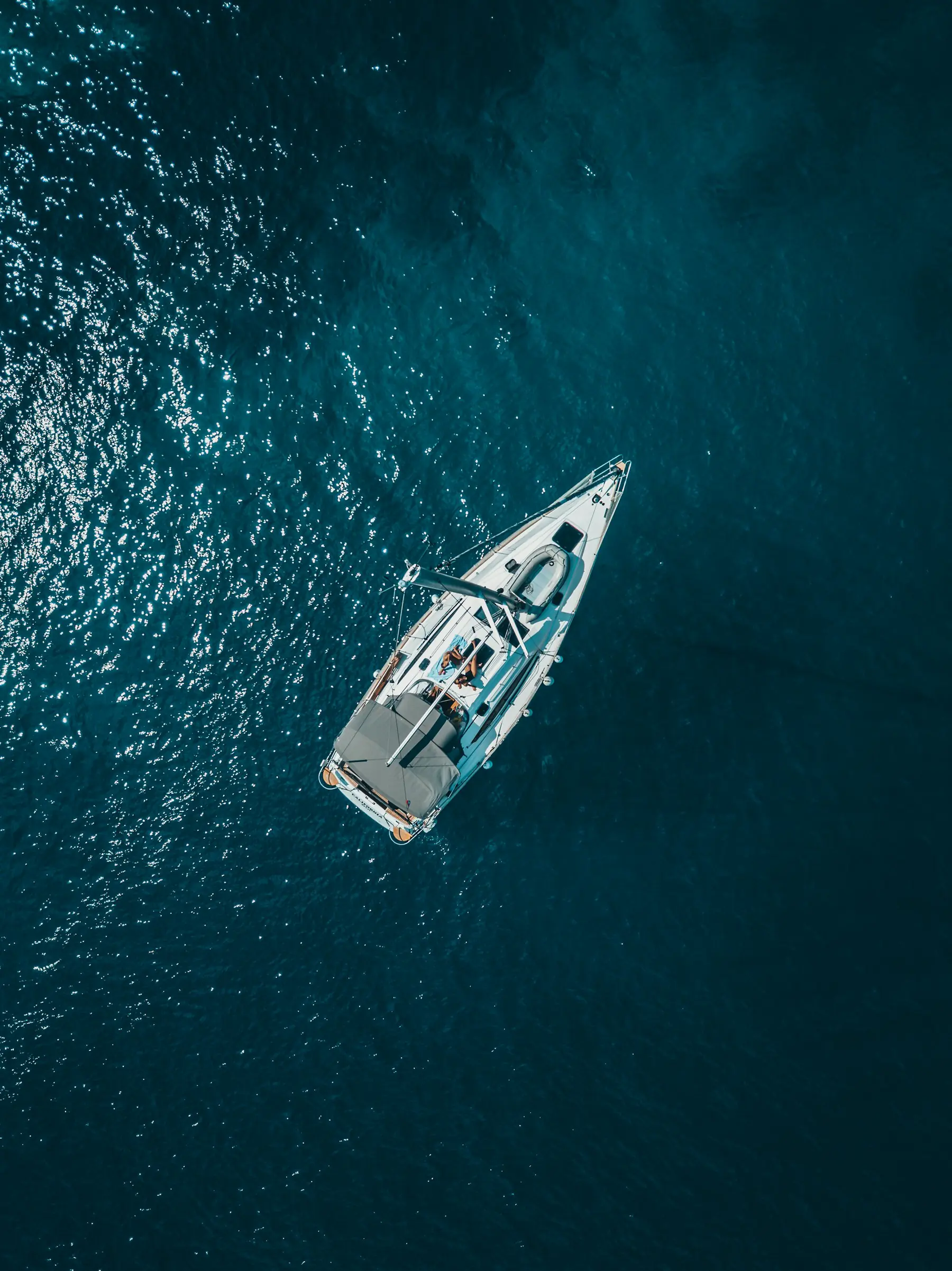
Sailboat under way, seen from above
Distributed architecture · 4 zones
Marine electrical & electronic engineering

Your boats' wiring, industrialised.

Architecture, schematics, harnesses, on-board integration. We bring automotive-grade documentation and industrial quality to shipyards, for new builds and refits alike.
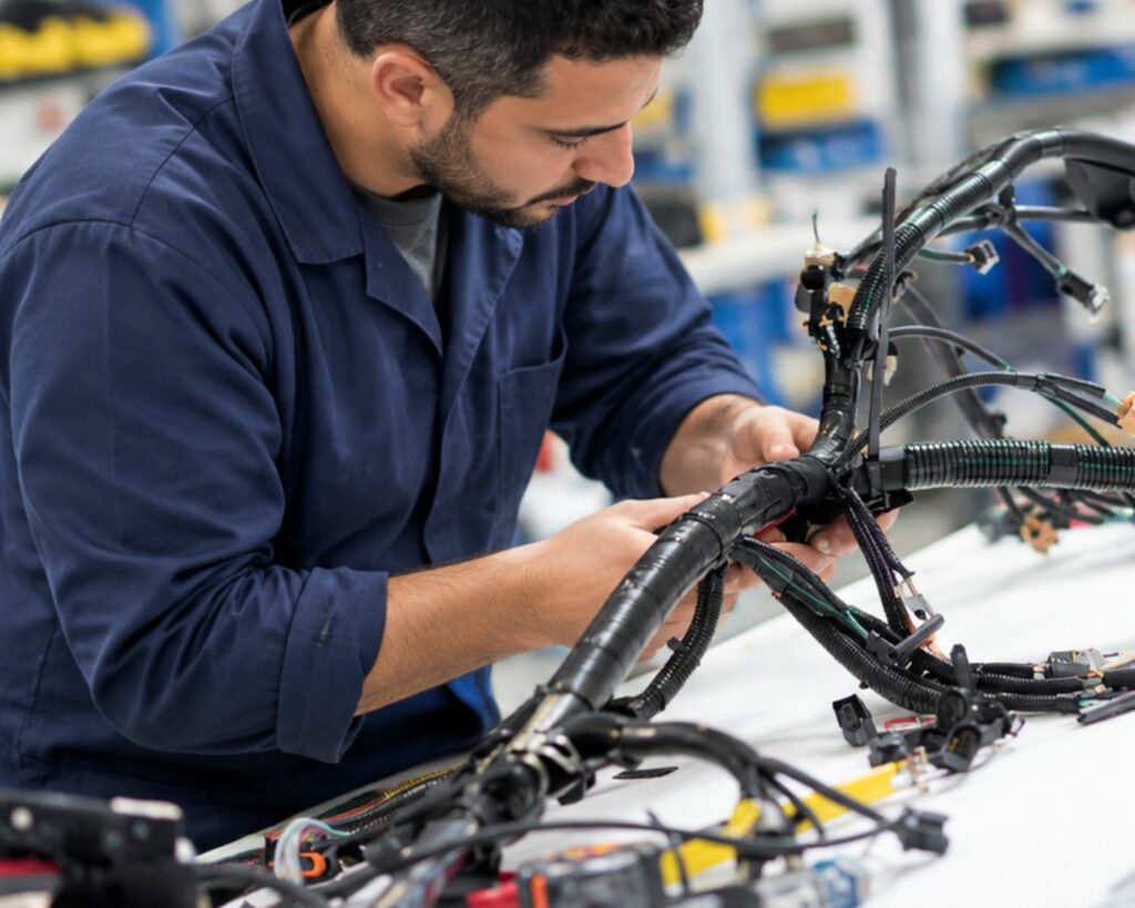
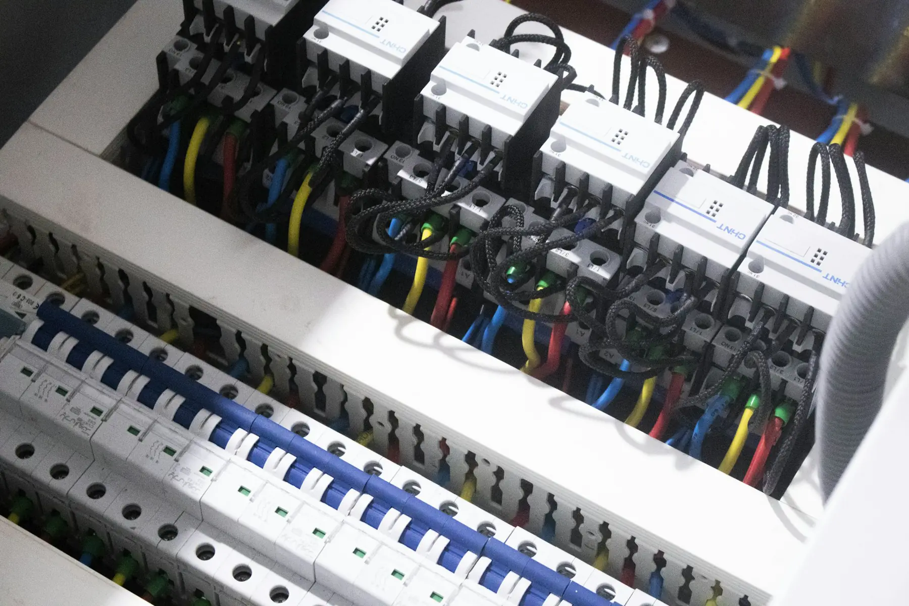
Prototypage et fabrication de faisceaux câblages - Harness Design and prototyping by Aliantec Neatly wired distribution panel with labelled circuits
The problem

On most boats, the electrical system is still designed while the cables are being laid.

  • ×No predefined harness above 55 feet: wiring is done on board, without drawings.
  • ×No two boats alike, even within the same series.
  • ×Inconsistent connector quality, the main source of failures.
  • ×Oversized harnesses that add weight to the boat.
  • ×No installation drawings: after-sales teams have to hunt for cables.
  • ×Costs and lead times that are hard to predict.
  • ✓Harnesses designed and built upstream, delivered ready to install.
  • ✓An identical installation on every unit in the series.
  • ✓Qualified industrial connectors, 100% tested.
  • ✓Optimised cross-sections: less copper, less weight.
  • ✓3D location views: fast after-sales troubleshooting.
  • ✓Budget and schedule under control from the design stage.
Our services

One point of contact, from architecture to delivered boat.

Entrust us with the full electrical scope, or just the step you are missing. Each building block produces documentation your yard can use.

Electrical architecture

Networks sized for your sailing programme.

  • 24 V / 12 V DC bus, battery bank
  • 230 V AC network, shore / genset / inverter
  • NMEA 2000 network, digital switching
  • Power budgets per zone

Schematics

Complete documentation, based on automotive standards.

  • Single-line diagrams, power distribution
  • Bills of materials (BOM), wire list
  • Terminal block list
  • 3D location views

Harnesses

Designed, prototyped, then produced in series, with electrical testing.

  • Optimised routing and cross-sections
  • Prototype, then industrialised series
  • Every wire labelled
  • Continuity and insulation testing

On-board integration

Installation, connection and commissioning at the yard.

  • Harness and panel installation
  • Equipment connection
  • Harbour and sea trials
  • Drawings updated to as-built
Harnesses

Harnesses built the automotive way.

Every harness is designed, prototyped and then produced through an industrial process. It arrives at the yard labelled, tested and ready to install.
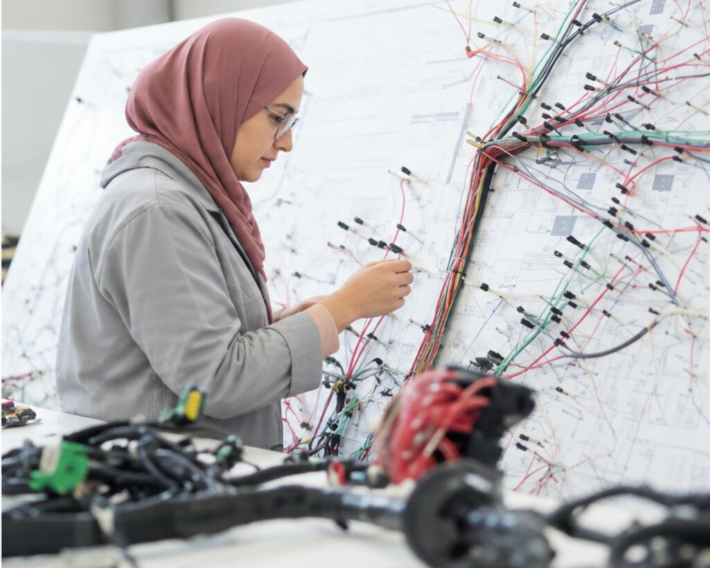
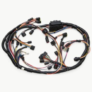
  1. Routing and cross-sectionsLengths and cross-sections calculated from the boat's 3D model.
  2. Wire-by-wire labellingEvery wire carries its ID, as listed in the wire list.
  3. Qualified connectorsControlled crimping, sealed connectors suited to the marine environment.
  4. 100% testingContinuity and insulation testing on every harness delivered.
Prototypage et fabrication de faisceaux câblages - Harness Design and prototyping by Aliantec
Harness on the formboard
Production de faisceaux câblages - Harness production by Aliantec
Finished harness
Conception de faisceaux câblages - Harness Design by Aliantec
Electrical testing
Distributed architecture

A module close to every zone.

Instead of a central panel and hundreds of wires, each zone of the boat has its own module, linked to the others by a single data bus. Less copper, short power cables, and control from any screen.

NMEA 2000 01 BOW WINDLASS 02 SALOON LIGHTING · COMFORT 03 ENGINE ROOM 24 V BANK 04 STERN WINCHES · PV
  • Power cables per zone< 2 m
  • Voltage drop, critical circuitsΔV < 3% (ABYC)
  • Mechanical bypass1 per zone
  • Data busSingle NMEA 2000
Schematics & location views

The whole boat, wired before it is built.

We rebuild the boat's 3D model (CATIA V5/V6 to Composer) to check every cable route, anticipate clashes and produce location views that the yard and after-sales teams can use.
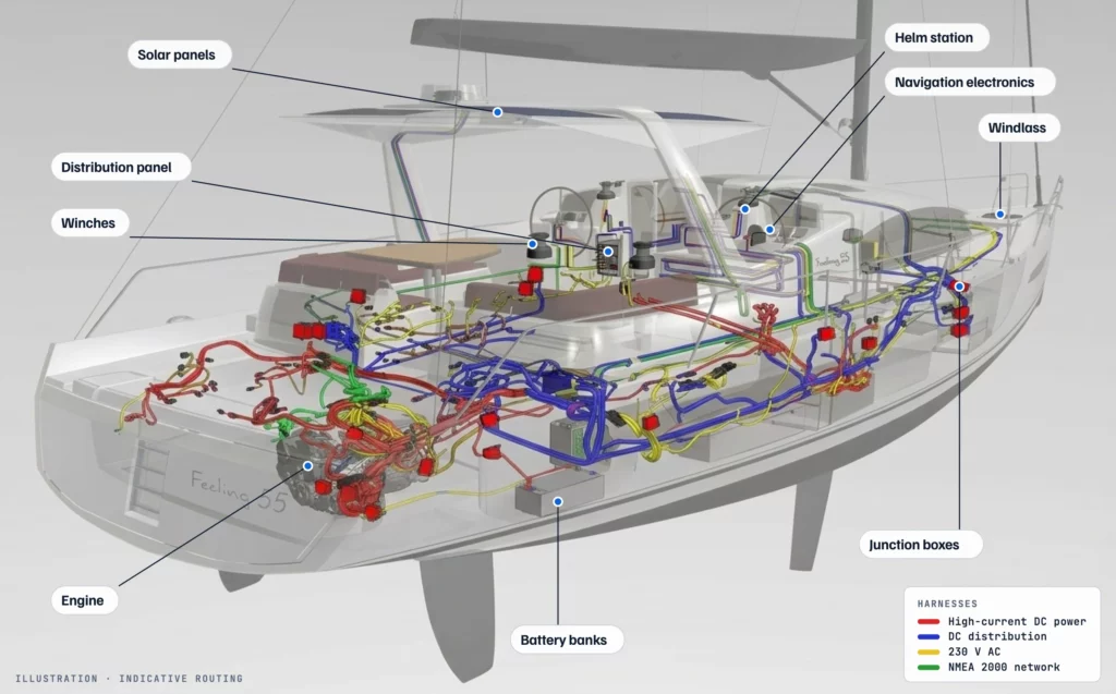
3D location view of the Feeling 55: DC, AC and NMEA 2000 harnesses and labelled connection points
Feeling 55: conceptual location view on the 3D deck model (simplified hull).
Measured on a real project · conventional vs distributed architecture
−0%Control wiring

The NMEA 2000 bus replaces hundreds of wires.

~0kgCopper saved

A direct gain in performance and heel.

<0%Voltage drop

On all critical circuits, ABYC compliant.

0zonesFull redundancy

Every zone remains controllable via a mechanical bypass.

Our method

Six phases, from specification to after-sales.

The cycle we apply in automotive, adapted to boatbuilding. For a series or a one-off.

PHASE 01

Design

Specifications, sizing, block diagrams and harness routing.

PHASE 02

Prototyping

First harness built, functional tests and adjustments.

PHASE 03

Industrialisation

Manufacturing processes, test protocols, production standards.

PHASE 04

Production

Harness manufacturing, inspection and testing of every unit.

PHASE 05

Integration

On-board installation, connection and commissioning at the yard.

PHASE 06

After-sales

Documentation, diagnostic tools and repair methods.

Deliverables

Every wire is documented.

You receive a complete electrical file that your production teams can read and your after-sales teams can use for the boat's entire life.

  • Wiring diagrams (PDF + source files)
  • Power distribution diagram
  • Bills of materials (BOM)
  • Wire list / cable list
  • Terminal block list
  • 3D views of the boat with harnesses
  • Location views per equipment item
  • As-built documentation
Safety & compliance

No single point of failure.

A three-level redundancy strategy: if the electronics fail, the electromechanical layer takes over; if everything fails, survival circuits remain hard-wired.

LEVELN1

Electronics

Redundant NMEA 2000 network: several independent control screens. If one fails, the others keep control of the whole boat.

LEVELN2

Electromechanical

A manual bypass on every module, accessible in each zone, with a diagnostic LED per circuit.

LEVELN3

Survival circuits

Bilge pumps, navigation lights, VHF and AIS stay independent of the digital system, on a dedicated supply.

ISO 13297ABYC E-11Division 241Category A · oceanISO 9001EN 9100
Ongoing project · Refit

Complete electrical refit of a Feeling 55.

On this 55-foot sailboat, we are redoing the entire electrical architecture: design, schematics, harness manufacturing and on-board installation. It is the first project where we apply our automotive method end to end on a boat.

BoatFeeling 55, monohull sailboat
TypeRefit
ScopeArchitecture → installation
StatusDesign in progress
Contact · Marine

Let's build your boats' electrical systems together.

Shipyard, naval architect or owner: tell us about your project and an engineer will reply within 48 business hours.

Emailcontact@aliantec.co
France+33 6 43 09 93 59
Morocco+212 6 60 77 98 79